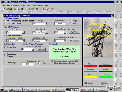
A voltage drop calculator is used to estimate the voltage drop in the circuit.Calculate the rated resistance based on the and reactance data of the NEC.
Basic Information of Voltage Drop Calculator:
However, do I do know if the cable is working normally? The National Electrical Code 210-19(a) (FPN 4) and 215-2(b) (FPN 3) advocate a voltage drop of 5% for circuits and 3% for branch circuits. Let’s take a glance at some samples of mistreatment of the equations within the sidebar (right). In our example, the vacant copper wire in the steel pipe is employed for the 480V tap. Use the facility issue column in NEC Table 9. Example 1: confirm the voltage drop. Feed a 20-amp #10 twisted wire into two hundred feet. Consistent with Table 9, our neutral resistance at 1,000 feet is 1.1 ohms. To fill within the counter, multiply it as follows: (2 x 0.866) x two hundred feet x 1.1-ohm x twenty A = 7620.8. Divide 7621 by a thousand feet to urge a fall of 7.7V, which is appropriate for our 480V circuit. #12 drops 11.8V. Increase the length to five hundred feet and drop 18V on #10. #12 drops 29B.Example 2: confirm the wire diameter to run 200 feet of stranded copper wire at 20 amperes. you’ll be able to modification the primary equation by pure mathematics to seek out the wire size, otherwise, you can use the following method: To fill the numerator, multiply as follows: 1.73 x 212. 9 ohms x two hundred feet x twenty A = eight9371.2 divide 89371.2 by the allowable fall 14.4 volts to urge 6207 mils. NEC Table 8 shows that line twelve meets the voltage drop recommendations. Example 3: confirm the length of the wire and place the No. ten copper stranded wire of the No. 20 circuits. To fill the numerator, please multiply like this: a thousand x 14.4V = 14400 To fill the denominator, please multiply by: (2 x 0.866) x 1.1 ohm x 20A = 38.104 Finally, divide the numerator by [*fr1] as follows: 14400 / 38.1044377 ft. If you utilize the #12 wire on an equivalent circuit, you may get 244 operating pins. Example 4: confirm the utmost load. Run number10 wires in a very two-hundred-foot chain. to finish the counter, multiply it as follows: a thousand x 14.4 V = 14,400. to urge the divisor, please multiply by the following: (2 x 0.866) x 1.1-ohm x 200 feet = 381.04 Finally, divide the dividend by the denominator as follows: 14400 / 381.04437A This circuit will be performed on every section conductor to be processed Operation of 37A. 2 of 200 feet high can handle 24A. *The number “0.866” is only used for the three-phase power supply. Convert “2” to “1.732” (square root of 3). For single-phase circuits, do not use “0.866” in the calculation. “CM” means round conductor mil, as shown in the figure As shown. Table 8 * To calculate the cable size, for copper, K uses 12.9, for aluminum, K uses 21.2. * “L” is the length of the unidirectional cable, in feet. “R” is the protection through 1000 feet. Practice NEC Table 9 as AC power joint. If you have a non-linear load, please use a column to point to the facility factor.
Formula One: Calculate the particular fall in volts fall = (2 x 0.866) x L x R x Amps / a thousand.
Formula two: Calculate the conductor cross-sectional space in mil CM = 2 x K x L x Amps / Allowable voltage drop Alternatively, you’ll be able to use formula 1 to perform pure mathematics calculations: R410002 allowable voltage drop / 1732 x L x A, so confirm the scale of the cable-supported the AC resistance.
Formula 3: Calculate the length in feet Length = 1000 x allowable voltage drop/(2 x 0.866) x R x Ampere Formula 4: Calculate the load in ampere = a thousand x allowable voltage drop/(2 x 0.866 ) X R x L.
There Are Four Main Reasons For The Decline OF Voltage Drop Calculator:
One of the main reasons is the alternative materials for cable production. The second is the second. The second is the choice of cable materials. Silver, copper, gold, and metallic elements are the metals with the most effective conductivity. Copper and aluminum are the most common materials used to make cables. Compared with silver and gold, the cost is relatively low. For a given cable length and size, copper can be more conductive than aluminum and has a lower voltage drop than aluminum. Wire diameter is another critical voltage drop that is considered important. A cable with a constant length, a cable with a larger diameter has less drop. If it is a pull-wire cable, every time one vi is reduced to the normal cable diameter, the cable diameter will double, and every time three standard cable diameters are reduced, the cross-sectional area of the cable will double. Ten times the diameter of fifty millimeters is five millimeters. However, the cable is another factor that affects the voltage drop. Shorter cables have a lower voltage drop than longer cables of the same size. If the length of the wire or cable is too long, the voltage drop will become too large. This is not a problem, but it may be a problem. Problems with cables connecting equipment, downhole pumps, etc. Eventually, the transmitted power will affect the voltage drop. An increase in the current through the wire causes the voltage to rise. fall. This is the maximum number of electrons that can be injected simultaneously. The term “capacity” refers to power in amperes. The cable depends on many factors. Of course, the main limiting factor is the base material of the cable. If AC flows through the cable, the change in speed will affect the allowable load. The use of the cable will affect the allowable load. The heat generated will affect the load capacity and voltage drop. Therefore, strict cable packaging guidelines must be followed. The choice of cable depends on two basic principles. It must withstand the current load without overheating. Basic thermal conditions during operation. In the second place. It must be properly grounded to (i) limit the voltage that people are subjected to a safe level, and (ii) allow the short-circuit current to open the fuse in a short period.
Calculating Voltage Drop:
Ohm’s law is a very simple law for calculating voltage drop calculator: Vdrop = IR where: I: the current through the wire, in amperes R: the wire resistance, the length of the span expressed in ohms, usually per-unit Kilo-ohms or ohms per 1000 feet as a unit. The cable is also there, also backward. Therefore, the formula for a single-phase circuit or DC circuit has the following form: Vdrop = 2IRL The formula for a three-phase circuit has the following form: Vdrop =√3IRL, where: I: current through the wire R: function of the resistance and length of the wire L: length in one direction.
Voltage Drop Formula And Calculation Of Basic Voltage Drop Formula:
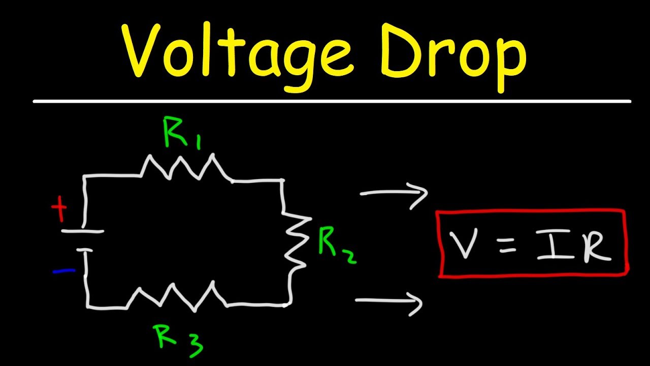
Basic voltage drop calculator formula: VD = IR … (Ohm’s law). Where; VD = voltage drop (in volts). I = current (amperes). R = resistance in ohms) However, this is not always the case and we cannot make the system turntable work with this basic voltage drop calculator formula (why?..See also the following cases.)
Pipe pressure drop formula- an approximate pressure drop formula commonly used by nurses. The capacity problem is 1, and the flow temperature is 75°C, so for Amor steel pipe, pickup = (2 xkx letter x I x D). / cm (single phase) network. For three phases, Wo is VD = (1.732) xkx Q x I x D) / cm cm = conductor cross-sectional area (mil) D = distance (in feet) I = circuit current in amperes Q = skin exposure , The size ratio of AC conductor resistance and DC resistance (RAC / R / DC) is greater than 2 / k = specific resistance Al = 21.2, copper resistance = 12.9.
single-phase and DC circuit formula drop:
when expressing the linear unit measurement value In feet, Cupid’s pica = I×RVD = I×(2×L×R / 1000)
Where; VD =
- voltage drop (in volts).
- I = cable current (in amperes).
- R = cable resistance, the unit is ohm (Ohm) [Ohm / kft].
- L = cable length (in feet).
The length of the cable is in meters.
VD = I × (2 × L × R / 1000)
where; VD = voltage drop in volts
- I = cable current in amperes.
- R = cable resistance, in ohms [ohms / km].
- L = cable length in meters.
Voltage drop calculation and formula for three-phase system .
Of three-phase three-wire system (delta connection)
VD = 0.866×I×RVD = 0.866×I×2×L×R / 1000 (applicable to three-phase four-wire system) (star connection )
VD = 0.5×I×RVD = 0.5×I×2×L×R / 1000
where;
VD = voltage drop in volts I = cable current in amperes R = in ohms (Ω) [Ω/ km or] Or (Ω/kft) cable resistance L = cable length in meters or feet.
Calculation of the cross-sectional area of the cable:
The unit of the cross-sectional area of the cable is in kilomils (circular kilometers) An = 1000×dn2 = 0. 025×92 (36-n)/19
Where;
An = the size of the cross-section “n” of the wire The kilogram is the unit, and the millimeter is the unit.
Kcmil = kilogram, a circle in one-millimeter
n= measurement number
d = square wire diameter in square inches 2 cross-sectional areas of the wire in square inches (2 inches).
An = (π/4)×dn2 = 0.000019635 × 92(36–n)/19.
Where;
An = calibrated cross-sectional area of wire diameter “n”, in square inches (inch2) n = caliWhere; bration number d = square wire diameter, in inches 2 wire cross-sectional area, in kilograms Unit)): An = (π/4) × dn2 = 0.012668 × 92 (36-n) / 19th.
where;
An = the cross-sectional area of the ``n’’ line in square inches (inches2). N = measuring equipment number.d = wire diameter in square inches square inch 2 wire cross-sectional area in kilometers (circular mils):
An = (π/4) × dn2 = 0.012668 × 92 (36-n) / 19.
Calculation of the cable cross-sectional area :
The cable cross-sectional area is in kilomils (circular kilometers and miles)
An = 1000 × dn2 = 0.025 × 92 (36-n) / 19.
Where;
An = the cross-sectional area of the wire gauge “n”, in units of thousand milliliters. Thousands of miles (Round Kilomiles) = Thousands of miles (Round Kilomiles). N = number of probe measurements d = square wire diameter in square inches. 2 The cross-sectional area of the cable is in square inches (in2) as the unit
An = (π/4) × dn2 = 0.000019635 × 92 (36-n) / 19.
Where;
An = the calibrated cross-sectional area of the wire diameter “n”, in square inches (inch2) n = calibration number d = the diameter of the square wire, in inches 2 cross-sectional area of the wire, in kilograms (kilograms)
An =(π/4)×dn2 = 0.012668×92(36-n)/19.
Where;
An = nominal cross-sectional area of "n" wires in square inches (inches2) n = square root diameter in inches d = cross-sectional area of wires in square inches 2 in kilograms (kg) The unit is the cross-sectional area of the wire
An = (π/4) × dn2 = 0.012668 × 92 (36-n) / 19.
The wire diameter:
The wire diameter is calculated using the formula in = 0.005×92 (36-n)/39. The wire diameter is inches. In inches, where “n” is the measurement number and “d” is the wire diameter (in inches).
Wire diameter, in millimeters (millimeters), according to the formula in = 0.127×92 (36-n)/39. Use millimeters (mm) as the unit.
“N” is the measured value, and “d” is the wire diameter in mm.
The formula for calculating the wire resistance:
(1) . Rn = 0.3048×10⁹×ρ/(25.42×An) where: R = the wire resistance of the wire (in ohms/km) n =# trace width ρ= rho = Unit resistance (in ohm m). An = the cross-sectional area of the gauge n# (square inch) (in2).
Or;
(2). Rn = 109×ρ/AnDonde; R = wire resistance (in ohms/km) n =# measuring equipment. P = Rho = resistivity, the unit is (Ohm·m). An = the cross-sectional area of the measuring device n# (unit: square millimeter (mm2))
The voltage drop formula and calculation formula at the end of the cable:
VEnd = V-VD
Where;
VEnd = power supply voltage at the end of the cable V = power supply voltage VD = voltage drop on the cable conductor The formula used to calculate the voltage drop in mils:
VD = ρP L I /A.
Where;
VD = voltage drop calculator, the unit is volt ρ = Rho = resistivity, the unit is (ohm-circular mil/ft). P = phase constant = 2 (for single-phase and DC systems) y = √3 = 1.732 (for three-phase systems) L = cable length in feet A = cable area in thousandths of an inch.
How to calculate the voltage drop on copper conductors (1-phase and 3-phase)?
The voltage drop calculator across the copper conductor can be calculated from the table below using the following simple formula: VD = fx I … L = 100 feet.
Example of Working Example of Voltage Drop Calculation:
Assume single-phase voltage is 220V, the current is 5A, conductor length is 100 feet and wire gauge (AWG) is 8. The #8 AWG wire is 0. 125 (from the table above), and this factor is 100 feet. Now enter the value in the above formula. VD = 0.125 x 5A x (100 feet)VD = voltage drop = 0.625 V.
SUMMARY: According to NEC (National Electrical Code) [210.19 A(1)] FPN No.4 and [215.2 A(3)] FPN No.2, the allowable pressure drop of the branch is 3%, and the final pressure drop is an acceptable partial circle, The branch circle is 5% to ensure correct and effective operation. For example, if the power supply voltage is 110V, the allowable voltage drop value should be.
Allowable voltage drop = 110 x (3/100) = 3.3 V.
How To Minimize The Voltage Drop?
NEC stated that the voltage drop in the branch circuit is 3%, while the voltage drop in the branch connected to the branch line is 5%, which will not cause major energy efficiency and overall circuit performance issues. However, if the voltage drop exceeds the specified percentage (5%), it may shorten the service life and increase the efficiency of circuits and equipment.
The following practical guidelines can minimize the voltage drop:
Increase the number or size of wires. Reduce power load. Reduce the length of the conductor. Reduce conductor temperature.
Increase the number of conductors or their size:
By increasing the number of conductors or their size, the resistance of the conductors can be successfully reduced, resulting in less voltage drop and higher efficiency. This process can also significantly reduce the total energy loss, which would otherwise be larger for standard-sized wires (as indicated by the general rules). Also, installing a neutral insulated conductor for each phase in the branch circuit can minimize the voltage drop caused by the reduced power load.
reduced power load:
By reducing the number of electrical equipment connected to the circuit to reduce the power load, power consumption and voltage drop can be reduced. However, in this case, you must also ensure that the number of sockets connected to each branch of the chain does not exceed six.
Note: In residential buildings, always pay attention that the insertion distance between sockets must not exceed 50 feet, and at least one external socket must be installed in each house. It should also be noted that each of these sockets must be connected to a separate circuit with a minimum rating of 12 AWG. This type of equipment can further reduce the voltage drop.
Voltage Drop Equation:
voltage drop equation
voltage drop = √3I (R Cosθ + X Sinθ) L3∅ voltage drop = 21 (R Cosθ + X Sinθ) L1∅ voltage drop = volts (V) I = current input amperage R = Conductive resistance in ohms/1000 feet X = inductance resistance of the conductor in ohms/1000 feet.
The same is 8-2.
Knowing the voltage drop, calculate the wire size.
Voltage drop 3∅=√3I(Z)LZ=Voltage drop=Vd√3IL√3IL Voltage drop 1∅=21(Z)LZ=Voltage drop=Vd2 IL 2 IL
Step (example)
- Suppose the voltage drop is 2%, for example, the reference voltage is 230 V, 1×vd = 0.02 (230).
- You should know the current and distance I = 30 A, L = 0.56 K ft 56 K ft. You need to know the power factor. … 85
- Solve after Z: Z = Vd / 2 IL = 4.8 V / 2 (30 A) (.5 Kft) = 16Ω/ Kft.
- Find Z in the table with 16Ω/Kft, 85 P. Directly bury the copper in the non-magnetic pipe.
Always use cables with Z-impedance less than 1,000 feet below the design.
Three-phase voltage drop:
Three-phase directly grounded cover
-
Vd = √3 (I) (Z) (L)
-
given: voltage 230 V, three-phase, 5 kW load P. = 1 heater, L = 480 feet.
-
Assumed pressure Reduced to 2%, the reference voltage is 230V. The maximum voltage drop enters the J.
-
Solve page of Z:
-
Z = voltage drop = 4.6 VDC.0254 ohms/ Kft.√3 IL = √3 (21.7A) ( .48Kft.)
-
Find Z in the table in the voltage drop table. @ P. = 1.0 Copper workbench, used for direct embedding at a temperature of 75°C.
Use the next smaller Z to indicate the wire diameter. Non-magnetic circuit.
500 MCM = 0.0270Ω/ Kft uses 600 MCM because the impedance is lower than the calculated.
power factor
PF = Cos θ = KW
KVA
Given 10 KW, 12 KVA Load, find PF: PF = 10KW = .8312KVA
Voltage Drop In A DC circuit- Resistance:
Consider a DC circuit with a 9-volt constant current source; three resistors of 67 ohms, 100 ohms, and 470 ohms; and a light bulb, all in series. DC power supplies, core wires (wires), resistors, and bulbs (loads) have resistance; all people use and consume the provided energy to a certain extent. Its physical properties determine how much energy. For example, the DC resistance of a conductor depends on the length of the conductor, cross-sectional area, type of material, and temperature. Measure the DC power supply and the first resistance (67 ohms). The potential on the first resistor is just below 9 volts. Current flows from the DC power source through the conductor (wire) to the first resistor; in this case, part of the supplied energy is “lost” due to the resistance of the conductor (the load is unavailable). The voltage drop on the power cable and return cable of the circuit. When measuring the voltage drop across each resistor, the measurement result is a valid number, which represents the energy consumed by the resistor. The larger the resistance, the more energy the resistance consumes, and the greater the voltage drop across the resistance. Ohm’s law can be used to check the voltage drop. In the intermediate circuit, the voltage is the current multiplied by the resistance. V = IR. Also, Kirchhoff’s circuit law states that in each DC circuit, the sum of the voltage drops on each circuit component is equal to the power supply voltage.
Voltage Drop In AC Circuits- Impedance:
In AC circuits, the resistance of current is generated by resistance, just like in DC circuits. However, AC circuits also contain a second type that is the opposite of current: reactance. The sum of resistance and reactance opposite to current is called impedance. Electrical impedance is usually represented by the variable Z, which is measured in ohms at a given frequency. Electrical impedance is calculated as the vector sum of resistance, capacitive reactance, and inductive reactance. The size of the impedance in an AC circuit depends on the frequency of alternating current and the permeability of the electrical conductors and electrical insulating components (including surrounding components), which depends on their size and distance. According to the law of DC circuits, resistance can be expressed by the formula E = I ZS, or the voltage drop in an AC circuit is the product of current and circuit impedance.
Conclusion: When current flows through the wire, it is squeezed by the potential (voltage) and must overcome a certain back pressure caused by the wire. Voltage drop is the amount of potential (voltage) loss caused by backpressure. When the current changes, this back pressure is called impedance. Impedance is a vector or two-dimensional quantity composed of resistance and reactance (the cumulative electric field’s response to changes in current). Direct current, back pressure is called resistance. Excessive voltage drops in the circuit can cause flickering or dim light burning, overheating of the glow plug, and overheating and burning of the engine. It should be less than 5% under full load conditions. This can be achieved by choosing the correct power cord and being careful when using extension cords and similar devices.
Frequently Asked Questions:
Q1: What kind of voltage drop is acceptable?
A: According to the National Electrical Code, at the furthest outlet of the branch circuit, if the voltage drop is 5%, normal efficiency can be achieved. For 120V and 15A circuits, this means that when the circuit is fully charged, the voltage drop at the farthest socket should not exceed 6V (114V).
Q2: How big is the pressure drop?
A: NEC recommends that the maximum total voltage drop of branches and branch circuits does not exceed 5%, and the maximum value of branches or branch circuits does not exceed 3% (Figure 1. This recommendation is a performance issue, not a safety issue.
Q3: How to maintain the voltage drop?
A: Four practical methods can be used to minimize the voltage drop problem: increase the number or size of conductors, reduce the load current in the circuit, reduce the length of the conductor, and reduce the temperature of the conductor.
Q4: Does the voltage across the resistor drop?
A: When a resistor is used in a circuit, the voltage and current can be reduced. The main function of the resistor is to limit the current. Ohm’s law states that increasing resistance will reduce voltage. The resistor is installed in a configuration called a voltage divider.
Q5: Why is voltage drop important?
A : It is necessary to determine the voltage drop on the long cable assembly. For long cable assemblies (over 50 feet), it is important to calculate the voltage drop due to potential hazards. Reasons include equipment power failure, potential damage to cables and wires, and safety hazards.
Q6: Will the resistor increase the voltage?
A: Voltage is the potential difference between two points. Resistance alone will never increase tension. It can have zero voltage drop or voltage drop. For safety reasons, the only way to detect the higher voltage on the resistor is to install another current source with a higher potential at this connection point.
Q7: What are the results of energy reduction?
A: Distributors, branches, and departments quickly reduced the output voltage of power equipment to unacceptable levels.
Q8: What is an energy reduction test?
A: Voltage drop is a form of electrical prediction that can be used to quickly identify high impedance problems in a circuit. Voltage drop is the voltage drop caused by modern current flowing through a resistor.
**Q9: How is the voltage calculated?**https://howtodiscuss.com/t/hazard/9114#
A: Ohm’s law and power need to find the voltage (V) [V = I x R] V (Volt) = I (Ampere) x R (Ω) to find the current, (I) [I = V÷R] I ((R) [R = V÷I] R (Ω) = V (Volt) ÷ I (Ampere) to obtain power P) [P. = V x I] P (W) = V (Volt) x I (Ampere).
Q10:What is the method for partial pressure?
A: Using the law of voltage division, we can see that the largest resistance results in the largest voltage drop I *R. Therefore, R1 = 4 V and R2 = 8V. The application of Kirchhoff’s law shows that since 4 V + 8 V = 12 V, the sum of the voltage drops around the resistance circuit exactly corresponds to the power supply voltage.